You ordered the parts, did the machine work, and now you have a 344ci small block Ford stroker sitting on the stand, Trick Flow CNC heads bolted on, a COMP cam waiting to drop in.
Now comes the step that separates a good engine from a great one: Degreeing the camshaft.
It sounds intimidating. It is not, once you understand what you are actually measuring and why each step matters. At Heavy Metal Engines, in our experience, this is the single most skipped step in street builds and the most regretted omission when a power number falls short of expectations.
This guide walks you through our process, exactly as we run it on builds like this 344ci stroker (302 based, .010 over, 3.400 inch stroke). The method works on any pushrod V8. The SBF specifics are just where we live.
Why Degreeing the Cam Actually Matters
Cam manufacturers grind their lobes to spec, but that does not mean your cam card numbers show up automatically in your engine. Timing chain stretch, sprocket keyway position, and manufacturing tolerances all stack up. A cam that is two degrees retarded is two degrees of power and throttle response left in the box.
You also have a stroker here. The 3.400 inch stroke on a 302 block changes the piston position relative to TDC and shrinks your piston-to-valve clearance window. Skip the verification step and you risk kissing a valve with a piston at high rpm. That is an expensive mistake.
Degreeing the cam costs you an afternoon. Skipping it can cost you an engine.
What You Will Need
- Degree wheel (large diameter is easier to read accurately)
- Positive stop tool (threaded into the spark plug hole)
- Dial indicator with magnetic base
- Pushrod length checker tool
- Checking spring (light tension, seats the lifter without loading the cam)
- Clay or machined spacers for piston-to-valve clearance check
- Your cam card (keep it on the bench, not in a drawer)
Step 1: Establish True TDC
This is the foundation. Get this wrong and every number downstream is wrong.
Use a Positive Stop, Not a Piston Stop Assumption
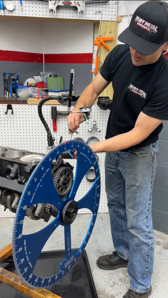
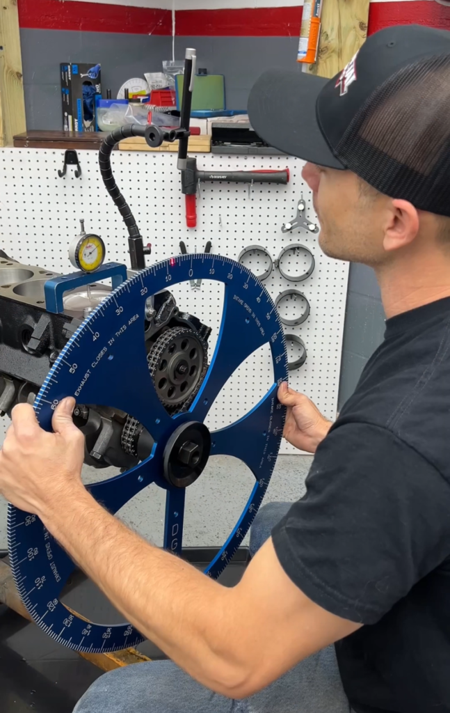
Install the positive stop tool into the spark plug hole on cylinder number one. Rotate the engine clockwise by hand until the piston contacts the stop. Mark the degree wheel. Rotate counterclockwise until it contacts the stop again on the other side. Mark again. True TDC is exactly halfway between those two marks.
Set the degree wheel to zero at that midpoint. Lock it down and do not touch it again.
Why a positive stop and not just a TDC probe? Because you are removing all mechanical slop from both directions. Guessing TDC with a dial indicator alone typically introduces one to two degrees of error. On a performance engine, that is real.
Alt text suggestion for image: Degree wheel mounted on SBF crankshaft snout with positive stop tool installed in cylinder one spark plug hole, engine on engine stand.
Step 2: Establish Correct Pushrod Length
Before you can read lobe events accurately, you need the right pushrod length. With hydraulic lifters, you are setting zero lash preload. With a roller tip rocker, you are also centering the roller on the valve tip.
Hydraulic Lifters and Zero Lash
Hydraulic lifters bleed down under pressure. For checking purposes, you want the lifter at zero lash, meaning the plunger is fully extended with no preload. A checking pushrod lets you find the exact length where the rocker just contacts the valve tip with no play and no preload.
Roller Tip Centering
Roller tip rockers are not forgiving of lateral misalignment. With the pushrod at the correct length, the roller should sweep straight across the center of the valve tip, with minimal side travel. Check this visually with the engine rotating slowly by hand. If the roller walks toward the edge of the tip, your geometry is off and pushrod length may not be the only factor.
Alt text suggestion for image: Adjustable checking pushrod installed on Trick Flow CNC head with rocker arm, roller tip visible on valve stem.
Step 3: Degree the Cam and Verify Intake Lobe Centerline
Now you are actually reading the cam. Lobe centerline is the most useful number. It tells you where peak lift occurs relative to TDC, and comparing it to the cam card tells you whether your cam is straight up, advanced, or retarded.
Reading Intake Lobe Centerline
Install the dial indicator on the lifter bore for the intake lobe on cylinder one. Rotate the engine through the full lobe event and find peak lift. Note the degree wheel reading at peak. That is your installed intake lobe centerline.
Compare it to the cam card. Most COMP cams will list the intake lobe centerline and give you a recommended installed centerline. Typically, advancing the cam two to four degrees improves low-end torque and throttle response. Retarding it shifts power higher in the RPM band.
Neither is wrong. It depends on what this engine is built to do. Know your target before you chase a number.
Step 4: Check and Verify Piston-to-Valve Clearance
This step is non-negotiable on a stroker build.
The longer stroke moves the piston higher at TDC relative to a stock 302. With aggressive cam timing and a large lobe, the exhaust valve is still closing and the intake is already opening right around TDC. That overlap window is where the piston is closest to both valves simultaneously.
Minimum Clearance Targets
In our experience on builds like this 344ci, you want at minimum:
- 0.080 inches on the intake valve
- 0.100 inches on the exhaust valve
Exhaust gets more clearance because the exhaust valve runs hotter and the head expands more under load.
How to Check It
The clay method is reliable and straightforward. Roll a thin layer of clay onto the piston crown around the valve relief areas. Install the head, torque it to spec, rotate the engine through two full revolutions, and pull the head. Slice the clay where the valves contacted it and measure the thickness with a caliper. That measurement is your clearance.
If you are short, you have a few options. Open the valve reliefs in the piston. Retard the cam timing slightly. Use a cam with a wider lobe separation angle. Each has trade-offs, and the right call depends on how this engine is set up overall.
This Is Not Guesswork. This Is Engineering.
Every number you collect during this process has a purpose. TDC gives you a clean reference. Pushrod length gives you correct geometry. Lobe centerline tells you whether the cam is where the manufacturer intended. Piston-to-valve clearance tells you whether it is safe to run.
Skip one and the others mean less.
At Heavy Metal Engines, every engine we build gets degreed. It is part of what makes the difference between a good engine and one that performs exactly the way it was designed to perform, every time you hit the throttle.
Want to See This Process on a Real Build?
If you want to see more of the shop process, follow along on Instagram at @heavymetalenginesusa.